nu am mai scris de mult timp , deoarece au fost tot felul de feluri de chestii de facut si reparat.
o sa imi fac acum un pic de timp si o sa scriu despre doua aparate defecte , incep cu primul aparat , o statie de emisie - receptie Yaesu FT897 . (urmatoarea postare o sa fie despre al doile aparat defect, si pe care l-am reparat)
LATER EDIT: MAI JOS GASITI SI REZOLVAREA LA UN DEFECT PE SQUELCH CARE I S-A INTAMPLAT
LA UN YAESU 897, UNUI ALT RADIOAMATOR.
deci, fara deci... intr-o buna dimineata vorbeam pe statie cu mai multi prieteni radioamatori , cand imi spune unul dintre ei , nea Ilie YO3FNM , bai nu te mai auzi cum te auzeai de puternic.
pff zic , cum ma sa nu ma aud cand eu vedeam pe ampermetru , putere consumata pe alimetare de 8 amperi.
receptie aveam , dar intradevar power metr-ul si swr metr-ul de la yaesu 897 nu mai imi aratau nimic. erau moarte de tot. numai in banda VHF , in UHF mergeau... ntz ntz , zic ... in sfarsit am crezut ca s-a ars vreo dioda la circuitul de indicare a puterii din statie sau swr . dar nu era asa. pt ca in 438 Mhz imi arata puterea , si cine stie yaesu 897 stie ca iesirea de vhf si uhf este pe aceasi mufa , implicit acelasi final de emisie ... (bine inteles cercetand mai in amanuntime schema se observa ca sunt filtre si comutatoare de emisie separate vhf si uhf )
statia consuma curent , aprox. 7-8 amp pe putere mare dar nu scoate pe antena mai nimic
scoate aprox jumate de watt. reflectometrul integrat in statie si powermetrul tot integrat in
statie nu arata nimic , adica 0 putere. in banda de 2 metri . daca intalniti aceste
simptome e posibil ca dioda incercuita din schema sa fie intrerupta . nu se face cui , se intrerupe
posibil din cauza ca pe placa e loc de 2 asemenea diode , ei au pus doar una. (si la putere de 50w nu tine)
eu ca o solutie de moment am pus o dioda 1N4007 . dar nu este recomandabil. acolo este o dioda pin. cu alte caracteristici.
avertizare: daca nu stii ce faci exact mai bine nu te apuca sa faci ce scrie mai jos ca parlesti ceva... sa nu zici ca nu ti-am zis (nu exagera cu nimic, masuratori de rf , tensiuni , caldura la letcon , deci fara excese :D )
am bajbait vreo 10 - 20 de minute uitandu-ma prin statie dupa piese inegrite sau ceva ars... inafara de o bobinuta mica , care era inegrita dar avea continuitate nu era nimic (o sa ii schimb pe viitor si acea bobinuta)(acum nu am avut chef)
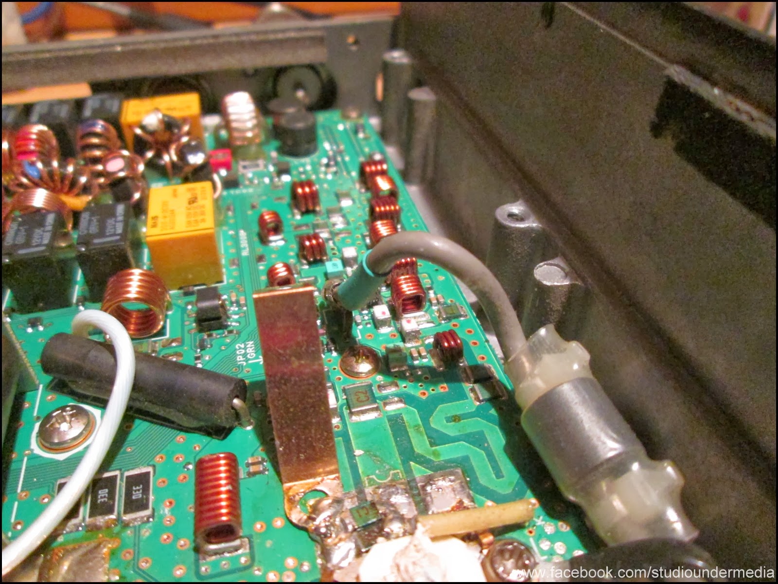
deci zic asa: cum faceam demult pe vremuri , cand reglam si verficam finali sau statii de emisie receptie, iau un beculet si ma apuc sa masor. in yaesu 897 se vede un fir cu rosu, acela vine de la tranzistorii prefinali.
am scos firul din soclul de pe placa cu finalii si am verificat cu un beculet de 24volti la 5wati , daca se aprinde cand dau emisie. se aprindea , asa slabut ca la vreo 2-3 wati de RF . zic boon . prefinalii nu sunt arsi.
consumul scazuse de la 8 amperi , cu mufa scoasa de la prefinali ,la vreo 2 amperi (cred)
inca o data va spun : nu masurati cu beculetul foarte mult timp, de ordinul secundelor , cateva secunde sa vedeti ca se aprinde , nu exagerati sa vedeti cum se aprinde beculetul , pt ca beculetul nu are impedanta care trebuie de 50 de ohmi sau cat ii trebuie acolo, deci ai vazut in 1 secunda 2 secunde ca se aprinde , gata nu mai tine mai mult in emisie ca arzi prefinalii , finalii etc etc..

firul rosu cu gri care se scoate si se masoara pe el , mare atentie sa nu faceti scurt sau ceva , deci masurat cateva secunde si gata , daca se inroseste filamentul e ok


tot cu beculetul, dupa cei doi condensatori era semnal , dupa dioda (care e una , in loc sa puna doua ca in schema in paralel, ei au pus o singura dioda, si pe schema apare cu 3 stelute a doua , probabil pt alte versiuni)


asadar s-a gasit defectul , o dioda pin de comutatie , de culoare alba din ceramica.

la indicatiile lui nea Marin YO3HGQ , acesta mi-a spus , pune linistit orice dioda de tensiune mare , cum ar fi BY255 sau altceva . eu am gasit prin piesele mele , un 1N4005 , pana la 600 de volti.


am scos dioda cu 2 letconuri in acelasi timp , unu in mana stanga unu in mana dreapta , si cu varfurile am ridicat dioda in sus , dioda smd care era acolo.
am gasit si din ce cauza s-a ars acea dioda : era un firicel de sarma mic mic cat o din aia de furnica , care a facut scurt pe una din bobinele din circuitul pi de pe iesire ... asa a fost sa fie , sa ajunga acea sarmultita mica , sau firicel de gunoi metalic ce era , sa faca scurt acolo.
am pus o dioda 1n4005 si gata treaba merge. nu am avut by255 si nea Marin a zis ca merge aproape orice dioda de voltaj mare . intradevar cand o sa gasesc o dioda pin originala , UM9957F care aia era acolo, o sa o schimb , pt ca pe acolo poate sa scape un pic din semnalul de pe receptie , dar sa nu mai intram in amanunte , ca oricum cine stie , stie .


am publicat acest defect pt ca sunt sigur ca se vor mai intalni si altii cu el , si decat sa caute ca mine sa benanaie aiurea pe net si sa nu gaseasca nimic , mai bine sa fie aici publicat. o sa pun si o traducere cu gugle translate ca sa se indexeze mai bine , defect , fault emisie yaesu ft897 :)
LATER EDIT: statia merge perfect cu acea dioda 1N.
un alt prieten radioamator, a patit cu Yaesu 897 alta buba:
nu ii mai merge squech-ul . dupa indelungi cautari , am gasit pe un site , ce se intampla ,atunci cand nu mai ii lucreaza sq la un 857 sau 897. din cauza reflectatei mari din unde scurte, se suprascriu valorile din EPROM-ul de service , acela care se acceseaza prin apasarea tastelor A-B-C la pornire .
defect squelci Yaesu 857-897: cum se manifesta : se vede pe s-metru purtatoarea , dar cu squelciul pus nu se aude
modulatia audio, adica nu se aude nimic in difuzor. cand se lasa squleciul jos de tot se aude.
va dati seama ca e enervant sa stai sa fasaie statia tot timpul. pt ca daca pui sq , se taie de tot
audio. chestia asta se intampla din cauza reflectatei din unde scurte. daca antena are reflecatata mare
statia protejeaza finalii , dar din constructie , are o hiba 857 si 897 . se dau peste cap scrierile
din memoria EProm de service . acel meniu ascuns care se acceseaza prin apasarea simultana a tastelor
A-B-C la pornire . indicat este atunci cand cumparati o statie de acest tip, atunci cand este in
mintile ei, daca e nou nouta, sa notati toate valorile prezente in acele campuri de service. e adevarat
sunt multe , vreo 100 si ceva , dar merita. (exista de asemenea in folderul cu fix squelci, o pagina de
net care va duce la un soft care face automat backup prin mufa de CAT , si salvati valorile in calc. personal)
AICI E LINKUL CATRE PAGINA CU SOFTUL CARE SALVEAZA MENIUL DE SERVICE
http://dl4cu.isa-geek.net/index.html
cititi acele pagini html salvate in folderul reparatie squlecy si acolo zice cum sa reparati squleciul.
pe scurt , trebuie sa emiteti cu o putere foarte mica , pe s-metru sa se vada S-1 sau mai mic, se apasa tasta
A pt a se memora valoarea de histerezis la S1 , apoi se merge la urmatoarea linie de service, si acolo se
memoreaza histerezisul pt S+40 , se da cu putere mare , si apoi se apasa tasta A pt memorare valoare squelci
maxim. in mod normal se procedeaza la alinierea aceasta cu un generator de semnal calibrat. ce am descris eu
aici este o solutie de criza. (nu am generator de semnal)
AICI ESTE SI UN LINK PE UN SERVER DIN ROMANIA CU FISIERLE DE 857 - 897
PE MASURA CE SE STRANG DIVERSE SOFTURI DE HAM-RADIO , VOR FI PUSE ACOLO
http://romeomanciu.no-ip.org:55555/MyWeb/yo3iva/kituri%20hamradio/yaesu%20ft897%20scheme%20defecte/defect%20squelch%20897/
FT-857D
Squelch Failure
If you have squelch turned on and
no sound is heard until the knob is turned
anti-clockwise thereby disabling it, then the following may fix the problem.
Background
Searching the internet found only one other person experiencing the same problem.
After a few email exchanges, it was found that we both were using HF with tuners
prior to the squelch fault. I was using the FC-30 ATU, and Dennis N8BMB was using
a manual tuner. (And, now (Oct 2010) I have received an email from G3ZQI with the
problem, including other settings that has changed like mine did.)
Is it possibly RF associated with high VSWR while tuning up?
If so, then maybe a component has changed value resulting in the final menu
value of almost 90 units away from the default CPU value in menu 13 (for example).
I'm not sure, but the problem was not fixed by resetting memories or the CPU.
ALSO - You may find that the signal strength on HF is reading
incorrectly and
the VSWR is also a little out of wack. After fixing the squelch problem, I had to
redo all the technical menu settings. For example, setting a S9 reading on the display.
Luckily I had another fully working unit I was able to use as a bench mark.
The Fix - by the book
You will need a VHF Signal Generator. (or read below how I did it)
1. Tune the radio to the 144MHz band and turn off the radio.
2. Access the tech menu by holding in A, B and C buttons while
turning on the radio with the squelch turned fully counter-clockwise.
3. Inject an RF signal from the sig gen at -15dBu output, with
+/-3.5kHz deviation FM Modulation of a 1 kHz tone.
4. Select menu item "13:FM-TH1" and press the A key.
5. Select menu item "14:FM-TH2" and press the A key.
6. Increase the sig gen output level to 0dBu.
7. Select menu item "15:FM-TI1" and press the A key.
8. Select menu item "16:FM-TI2" and press the A key.
9. Hold the function key in long enough to accept the new data.
Here is what I had to do.
I don't have a signal generator so I improvised with a hand held and a dummy load.
I pressed the A key for menu 13 and 14 while on low power and whistling into
the mic and pressed the A key for menu 15 and 16 while on high power.
This did not work, although values were entered about 80 higher than the
original value.
WHAT DID WORK was to put the squelch knob up at about 3/4 clockwise and did the
same and now I can actually use the squelch quite successfully on all modes / bands.
Menu Number - Orig Value - New Value
13 90 178
14 95 179
15 4 170
16 4 170
These new values are possibly not correct, but will update when I can do the
fix with the proper signal generator.
Well the sig gen was
no improvement. !! But setting the other menus to correct values
seemed to improve the operation all round.
seemed to improve the operation all round.
Service Menu's for my FT857D in the Car and in the Shack |
|||||
| Menu | Content | Description | Remarks | Car | Shack |
| 001 | HF1RXG | CW 1.825,07 | The higher, the more sensitive the RX is | 200 | 203 |
| 002 | HF2RXG | CW 7.043,55 | 107 | 98 | |
| 003 | HF3RXG | CW 21.070,00 | 198 | 214 | |
| 004 | 50MRXG | CW 50.095,00 | 131 | 148 | |
| 005 | VHFRXG | CW 145.375,00 | 149 | 218 | |
| 006 | UHFRXG | CW 433.425,00 | 90 | 128 | |
| 007 | SSB-S9 | CW 21.070,00 | The higher, the more shown level | 61 | 85 |
| 008 | SSB-FS | CW 21.070,00 | 191 | 54 | |
| 009 | FM-S1 | FM 145.375,00 | 60 = S0 The higher, the higher the S-value is |
71 | 73 |
| 010 | FM-FS | FM 145.375,00 | 99 | 103 | |
| 011 | DISC-L | FM 145.375,00 | Press "A" at test signal given "-3kHz" and "+3kHz" | 53 | 49 |
| 012 | DISC-H | FM 145.375,00 | 80 | 75 | |
| 013 | FM-TH1 | FM 145.375,00 | open/close level without RX signal (Threshold / Hysteresis) |
175 | 97 |
| 014 | FM-TH2 | FM 145.375,00 | 175 | 92 | |
| 015 | FM-TI1 | FM 145.375,00 | on RX signal of 3 dBµ (Tight = Enge) |
170 | 5 |
| 016 | FM-TI2 | FM 145.375,00 | 170 | 5 | |
| 017 | VCC | at Ub=13,8V | 138 | 138 | |
| 018 | HF1-IC | CW 1.825,07 | the lower, the more sensitive the protection is | 92 | 101 |
| 019 | HF2-IC | CW 7.043,55 | 84 | 94 | |
| 020 | HF3-IC | CW 21.070,00 | 98 | 121 | |
| 021 | 50M-IC | CW 50.095,00 | 125 | 165 | |
| 022 | VHF-IC | CW 145.375,00 | 75 | 81 | |
| 023 | UHF-IC | CW 433.425,00 | 75 | 81 | |
| 024 | HF1-MAX | CW 1.825,07 | 100W | 172 | 171 |
| 025 | HF1-MID2 | CW 1.825,07 | 50W | 111 | 111 |
| 026 | HF1-MID1 | CW 1.825,07 | 10W | 33 | 33 |
| 027 | HF1-MIN | CW 1.825,07 | 5W | 14 | 15 |
| 028 | HF2-MAX | CW 7.043,55 | 100W | 172 | 172 |
| 029 | HF2-MID2 | CW 7.043,55 | 50W | 109 | 110 |
| 030 | HF2-MID1 | CW 7.043,55 | 10W | 31 | 31 |
| 031 | HF2-MIN | CW 7.043,55 | 5W | 13 | 14 |
| 032 | HF3-MAX | CW 21.070,00 | 100W | 171 | 172 |
| 033 | HF3-MID2 | CW 21.070,00 | 50W | 110 | 110 |
| 034 | HF3-MID1 | CW 21.070,00 | 10W | 31 | 31 |
| 035 | HF3-MIN | CW 21.070,00 | 5W | 13 | 14 |
| 036 | 50M-MAX | CW 50.095,00 | 100W | 158 | 160 |
| 037 | 50M-MID2 | CW 50.095,00 | 50W | 101 | 102 |
| 038 | 50M-MID1 | CW 50.095,00 | 10W | 51 | 51 |
| 039 | 50M-MIN | CW 50.095,00 | 5W | 11 | 12 |
| 040 | VHF-PO-MAX | CW 145.375,00 | 50W | 91 | 93 |
| 041 | VHF-PO-MID2 | CW 145.375,00 | 20W | 44 | 45 |
| 042 | VHF-PO-MIN | CW 145.375,00 | 5W | 7 | 8 |
| 043 | UHF-PO-MAX | CW 433.425,00 | 20W | 123 | 120 |
| 044 | UHF-PO-MIN | CW 433.425,00 | 5W | 15 | 16 |
| 045 | HF1-TXG | USB 1.825,47 | the higher, the higher the TX amplification of driver is (alignment that 5 W FM come out for sure) | 45 | 64 |
| 046 | HF2-TXG | USB 7.043,55 | 48 | 43 | |
| 047 | HF3-TXG | USB 21.070,00 | 49 | 55 | |
| 048 | 50MTXG | USB 50.095,00 | 30 | 31 | |
| 049 | VHFTXG | USB 145.375,00 | 39 | 35 | |
| 050 | UHFTXG | USB 433.425,00 | 62 | 55 | |
| 051 | ALC1-M | USB 21.070,00 | measured: 180 -> value + 4 dots |
245 | 246 |
| 052 | ALC-M | USB 21.070,00 | 115 | 110 | |
| 053 | HF1-REV-ALC | CW 1.825,07 | the lower, the more sensitive protection and reduction of output power | 65 | 73 |
| 054 | HF2-REV-ALC | CW 7.043,55 | 56 | 64 | |
| 055 | HF3-REV-ALC | CW 21.070,00 | 56 | 61 | |
| 056 | 50M-REV-ALC | CW 50.095,00 | 44 | 53 | |
| 057 | VHF-REV-ALC | CW 145.375,00 | 74 | 50 | |
| 058 | UHF-REV-ALC | CW 433.425,00 | 148 | 131 | |
| 059 | CW-CAR-LEVEL | CW 21.070,00 | 152 | 142 | |
| 060 | AM-CAR-LEVEL | AM 21.070,00 | the lower the higher modulation level | 141 | 130 |
| 061 | DEV-W | FM 145.375,00 | deviation = 5 kHz | 221 | 214 |
| 062 | DEV-N | FMN 145.375,00 | deviation = 2.5 kHz | 113 | 110 |
| 063 | MOD-MTR | FM 145.375,00 | the lower, the more meter level | 201 | 204 |
| 064 | DTMF-DEV | FM 145.375,00 | the higher, the more deviation | 40 | 43 |
| 065 | CTCSS-DEV | FM 145.375,00 | the higher, the more deviation | 230 | 230 |
| 066 | DCS-DEV | FM 145.375,00 | the higher, the more deviation |
168 | 168 |
| 067 | LSB-CAR-POINT | LSB 21.070,00 | 0 | -10 | |
| 068 | USB-CAR-POINT | USB 21.070,00 | 2 | -7 | |
| 069 | VSWR2 at 10W | CW 14.070,00 | 14 | 20 | |
| 070 | VSWR3 at 10W | CW 14.070,00 | 38 | 45 | |
| 071 | ATAS-TEST | LSB 14.070,00 | |||
| 072 | AMTR-TEST | LSB 14.070,00 | |||
| 073 | HTEMP-Threshold | LSB 14.070,00 | 38 | 38 | |
| 074 | FTEMP-Threshold | LSB 14.070,00 | 102 | 102 | |
Problems with Service Menu Memory Corruption
I must confess I've encountered several problems with my FT-897 during the time that I've owned it. Last fall, I was operating a contest and using power on 160/80/40/20m. The rig seemed to be performing flawlessly. I stopped for dinner, expecting to come back later and get into the digital portion of the contest. However, when I powered the rig back on, it immediately did an uncommanded full microprocessor reset and would no longer put out more than about 30W on the 160m band. A more studied investigation revealed other idiosyncrasies: For instance, the AGC did not appear to be linear anymore and the S-meter readings bore little resemblance to reality. However, the rig continued to more-or-less function.After some detailed investigating, which included poring over the service manual and the internet, I discovered that the FT-897 has a Service Menu which consists of 74 alignment parameters. Some values in the menu on my rig had been set to some rather curious values – there was a cluster of Service Menu items all set to "64" and another all set to "128". I later determined that all the values had been reset to their initial pre-alignment defaults. The Service Menu is normally programmed as part of the rig's alignment procedure. The values control things like the gain of internal stages, or the per-band current limits of the finals. They are stored in the rig's EPROM memory. Think of them as the firmware equivalent of an alignment potentiometer or trimmer cap: The correct values are specific and unique to each transceiver – you can't just find them on the internet and reprogram them into your unit, although these modern rigs are manufactured to close enough tolerances that comparing the values between them can be of some utility. But, to reiterate, if they become corrupted, you have to re-perform the alignment procedure described in the Service Manual, unless you know what they were set to originally in your unit.
I suspect that during the time I was contesting and running power on bands I don't normally do this on, some RF crept into the rig and corrupted some of these values. Or perhaps my CAT cable is insufficiently shielded and RF on the cable was interpreted as bogus commands to the rig, some of which might include commands to store new data in the EPROM. Whatever the root cause, on reboot a checksum most likely failed, causing the rig to reset the service menu items to their defaults. At least that's my theory.
MAKE A BACKUP OF YOUR SERVICE MENU: If I had just known all this and saved the values from my rig prior to this incident, although it might have taken some time, I could have reprogrammed them back into the rig after the data corruption had occurred. With 20/20 hindsight, I would urge all FT-897 owners to go into their Service Menu and copy down these values before an unfortunate event leads to their loss. To enter the Service Menu, power the rig on from the front panel power button while simultaneously depressing the A, B, and C buttons. You'll hear the distinctive "diddle-diddle-diddle" sound that indicates you are in the Service Menu, and the first item "01:HF1RXG" will display on the rig's screen, along with its value. You can scan through the Service Menu list by using the MEM/VFO knob. The values can be changed using the main tuning knob, but don't do this. Instead, copy down each Service Menu number and its value in turn. On my FT-897D there were 74 of them. After you have copied all the values, exit the Service Menu by powering the rig off, or pressing and holding the "F" key to rewrite the values if you've changed any of them. Then, if you ever experience an event where your EPROM becomes corrupted, you can recover from it without having to pull out the scope and signal generator.
A Yaesu Design Flaw Leads to Filter Failure?
Several years ago, complaints from FT-897 and FT-857 owners began surfacing about the sudden onset of internal static in their receivers. The ancillary evidence suggests that this problem exhibits itself in rigs manufactured since around 2007. Darrel Emerson, AA7FV, produced a writeup about the problem, which he attributes to a design flaw in these rigs. Specifically, he alleges the AM filter should be DC-isolated, but is not, resulting in the switching voltage eventually breaking down the ceramic filter. He also explains how to correct the problem, although it involves some fairly intricate work on the main board to add several surface-mount components.The response to Darrel's proposed modification has been mixed. While the addition of the DC isolation certainly seems to correct the problem — even, it has been reported by some, in rigs where the filter has already broken down — to my knowledge Vertex Standard has refused to comment on the entire issue and tackles the repair by swapping out the defective filter for a new one, without further modification. Since the FT-897 had been around for a number of years before this issue was widely seen, I'm inclined to believe that the ceramic filter probably went through a cost-saving redesign in 2007 time frame, which precipitated the problem, and that when Vertex Standard became aware of the issue, they substituted the part for one which, like its predecessors, is better able to withstand the DC bias voltage the FT-897 imposes on it. However, this is only supposition on my part, and since Vertex Standard is not talking publicly about this, only time will tell if the problem has been resolved.
Good day my dear .I have not written for a long time because they were all sorts of kinds of stuff to do and repaired.I will now make a little time and write about two defective devices , starting with the first device, a radio station - Yaesu FT897 reception . ( next post will be about the second device defect , and I repaired )So , without so ... a good morning on the station talking with friends hams , when I say one of them , Uncle Elijah YO3FNM , hei you not hear how loud you could hear .pff say , as I do not hear me when I saw the ammeter , power supply units consumed per 8 amps.reception was , but really the metr power and SWR meters- from the 897 YAESU not show me anything. all were dead . only VHF , UHF walked in ... NTZ NTZ , say ... I finally thought to burn any indication diode power circuit of the station or SWR . but it was not. For 438 Mhz that shows me the power , and who knows knows 897 YAESU VHF and UHF output jack is the same hence the same final broadcast ... ( May well understood thoroughly researching the scheme are seen as emission filters and switches separate VHF and UHF )Warning : if you do not know better do not go exactly do you write below as parlesti something ... Do not say I did not say ( do not overdo anything , RF measurements , voltages, heat the letcon , so no excesses : D) I grope about 10-20 minutes glancing through the station after blackened pieces or something burning ... out of a small coil , which was blackened but have continuity there was nothing (one would change the future and the coil ) ( now I felt like )So I say this: as long doing the old days , you adjust the end Checker emission or reception of stations citizen band through the 1990s, taking a lighted I start measure . in YAESU 897 shows a red wire , that comes from predefinid transistors .I removed the wire from the socket on the board and I checked finalii lighted by the 5wati 24volti if you give emission lights . is lit , so skinny as 2-3 watts of RF . i say good . prefinalii not burned . (ha ha ha "prefinalii" not burned , hahahaha google translate rulss :)))) )low- to 8 amps, the plug removed from the pre-finished , about 2 amps (I think)I say again : no indicator light measured with very long, of the order of seconds , a few seconds to see the lights , do not overdo it to see how light is illuminated , the indicator light for no impedance to be 50 ohms or how long it be there, so you saw 1 second 2 seconds to turn on, ready not to broadcast that you burn more prefinalii , finalii etc etc. ..red wire is gray out and measure him , carefully not to do something short , so measured a few seconds and ready , turn red if the filament is ok
I put the cable back and started to measure the emission by the end , the scheme after two capacitors in series with the antenna circuit . Then I found that after the diode in the picture below does not pass the RF signal .all the indicator light after the two capacitors was signal after the diode (which is one second instead of putting the scheme in parallel , they put a single diode , and the scheme appears with three stars to two , perhaps for other versions )therefore find fault , pin diode switches, ceramic white .the indications of Uncle Marin YO3HGQ he said , quietly put any high voltage diode such as BY255 or something. I found through my pieces , a 1N4005 , up to 600 volts.I removed the diode 2 letconuri whilst one in the left hand one in your right hand , and with the tips I picked up diode , smd diode that was there .I found and why it burned the diode : it was a tiny little wire as one of those little ant , who made one of the coils short circuit on the output pi ... it was to be, to get the sarmultita small trickle of trash metal or what it was doing there soon .I put a 1N4005 diode and ready to go work . I had by255 and Uncle Marin said go almost any high voltage diode . indeed when you find a pin diode original UM9957F that that was there, to exchange , for that there can escape a bit from the reception signal , but not to go into details, anyway who knows, knows .I published this defect for I am sure they will meet others with him, than to look like me benanaie elsewhere on the net and not find anything better to be here published . I put a translation to translate Guglia to index the better, faulty emission foul YAESU ft897 :)
Niciun comentariu:
Trimiteți un comentariu